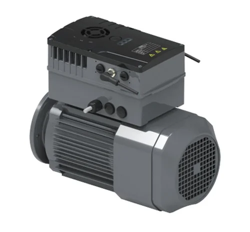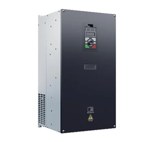
Distributed VFD Placement with FD500
A distributed layout for the FD500 Distributed Inverter starts by deciding where each drive location sits relative to the load, so cable runs and heat zones are planned before installation.
Cabling Paths Around the Drive
When routing cables for the FD500 Distributed Inverter, keep the drive’s power path and the control path distinct in the layout drawing, especially where the FD500 Distributed Inverter is placed away from a central panel.
Heat and Airflow Zones
Heat around the FD500 Distributed Inverter should be treated as a layout issue: place the drive where its installation area is not crowded by other equipment, and reserve space around it so heat is not trapped.
Using AD1000PLUS in Mixed Layouts
In mixed VFD layouts, the AD1000PLUS High-Performance Vector Inverter can be named alongside the FD500 Distributed Inverter as a separate drive location; keep each drive’s cable entry and heat zone clear in the layout.
Layout Review Checklist
Before finalizing a distributed VFD layout for the FD500 Distributed Inverter, review drive locations, cable routes, heat separation, and any AD1000PLUS High-Performance Vector Inverter positions in the same plan.